


Page 6 - october22_previewaa.indd
P. 6
TAP TIMES          -6-                              OCTOBER 2022


          High-power socket designp (from 4)                    through each functional pin on the pack
                                                                age.  Parallel pins help, but over the life
                                                                of the test, the highest load will be borne
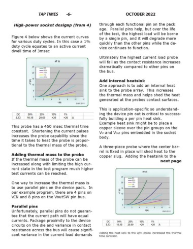
        Figure 4 below shows the current curves                 by a single pin, and it will degrade more
        for various duty cycles. In this case a 1%              quickly than the other pins while the de-
        duty cycle equates to an active current                 vice continues to function.
        dwell time of 3msec

                                                                Ultimately the highest current load probe
                                                                will fail as the contact resistance increases
                                                                dramatically compared to other pins on
                                                                the bus.


                                                                Add internal heatsink
                                                                One approach is to add an internal heat
                                                                sink to the probe array.  This increases
                                                                the thermal mass and helps shed the heat                   (
                                                                generated at the probes contact surfaces.

                                                                This is application-specifi c so understand-
                                                                ing the device pin out is critical to success-
                                                                fully building a per pin heat sink.
                                                                Example heat sink might be to place a
        This probe has a 450 msec thermal time                  copper sleeve over the pin groups on the
        constant.  Shortening the current pulses                Vin and Vout pins embedded in the socket
        increases the probe capability since the                body.
        time it takes to heat the probe is propor-
        tional to the thermal mass of the probe.                A three-piece probe where the center bar-
                                                                rel is fi xed in place will shed heat to the
        Adding thermal mass to the probe                        copper slug.  Adding the heatsink to the
        If the thermal mass of the probe can be                                                        next page
        increased along with limiting the high cur-
        rent state in the test program much higher
        test currents can be reached.


        One way to increase the thermal mass is
        to use parallel pins on the device pads.  In
        our example program, there are 4 pins on
        VIN and 8 pins on the VoutSW pin bus.


        Parallel pins
        Unfortunately, parallel pins do not guaran-
        tee that the current path will have equal
        currents. Package proximity to the device
        circuits on the die and variance in contact
        resistance across the bus will cause signifi -
        cant variance in the current load demands               Adding the heat sink to the QFN probe increrased the thermal
                                                                time constant.

